

Organic Photovoltaics: An Introduction
What are Organic Photovoltaics ?
Organic photovoltaics (OPVs) have received widespread attention due to promising qualities, such as solution processability, tunable electronic properties, low temperature manufacture, and cheap and light materials. Whilst several other photovoltaic technologies have higher efficiencies, OPVs remain advantageous due to the low material toxicity, cost, and environmental impact. They have exceeded certified efficiencies of 13% to date, close to efficiency values obtained by low-cost commercial silicon solar cells.1,2 An overview of solar cell technologies, the solar spectrum, and important physical parameters used to measure cells can be found in the Solar Cells: A Guide to Theory and Measurement, which is suggested as further reading to this article.
Please choose our organic photovoltaics (OPV) online according to your needs!
-
What is an OPV?
An OPV cell is a type of solar cell where the absorbing layer is based on organic semiconductors (OSC) – typically either polymers or small molecules. For organic materials to become conducting or semiconducting, a high level of conjugation (alternating single and double bonds) is required. Conjugation of the organic molecule results in the electrons associated with the double bonds becoming delocalised across the entire length of conjugation. These electrons have higher energies than other electrons in the molecule, and are equivalent to valence electrons in inorganic semiconductor materials.
Laboratory OPV cells manufactured on glass.
However, in organic materials, these electrons do not occupy a valence band but are part of what is called the ‘highest occupied molecular orbital’ (HOMO). Just like in inorganic semiconductors, there are unoccupied energy levels at higher energies. In organic materials, the first one is called the lowest unoccupied molecular orbital (LUMO). Between the highest occupied molecular orbital (HOMO) and lowest unoccupied molecular orbital (LUMO) of the OSC is an energy gap - often referred to as the band gap of the material. With increased conjugation, the band gap will become small enough for visible light to excite an electron from HOMO to LUMO. -
How do OPVs work?
As with other PV technologies, the purpose of an OPV is to generate electricity from sunlight. This is achieved when the energy of light is equal to or greater than the band gap, leading to absorption and excitation of an electron – from the HOMO to the LUMO. The excited electron will leave behind a positively-charged space known as a ‘hole’. Due to the opposite charges of the hole and electron, they become attracted and form an electron-hole pair, also known as an ‘exciton’. To remove the charged particles from the solar cell, the electron-hole pair must be separated, and this process is known as ‘exciton dissociation’.
Typically in an inorganic semiconductor, the attraction between the electron and hole (known as the exciton binding energy, Eb) is small enough to be overcome by thermal energy at room temperature (approximately 26 meV).3 This is due to a high dielectric constant – meaning there is significant screening between the electron and hole, reducing the attraction between them. The ease in separating the electron and hole allows easy exciton dissociation.
In contrast, OSCs have low dielectric constants, giving large Eb values in the range of 0.3-0.5 eV.4 As a result, exciton dissociation cannot be achieved by thermal energy alone in OSCs. To overcome this, at least two different OSCs are needed within an OPV. The energy levels between the two different OSCs are offset, with the difference being greater than Eb¬, allowing exciton dissociation to occur at the interface between them.
Depending on how the exciton dissociates, the OSCs are classified as either a ‘donor’ or ‘acceptor’ (referring to whether the electron has been donated by a material, or accepted by a material). In most OPVs, the donor will absorb the most light, and therefore the exciton will be generated on this material. At the interface with the acceptor, the exciton will dissociate. The electron will be donated to the acceptor material, which has a deeper HOMO and LUMO level, whilst the hole remains on the donor material.
The donor-acceptor band gap offset typical in an OPV, used to overcome exciton binding energy and facilitate dissociation.
-
The steps that govern OPV function
The steps that govern OPV function can be summarised as:
1. Absorption of incident, light leading to exciton generation
Light with high enough energy levels will be absorbed by the OSC and excite electrons from the HOMO to the LUMO to form an exciton. If the energy of light being absorbed is greater than the band gap, the electron will move to a higher energy level than the LUMO and decay down. This process is known as ‘thermalisation’, during which the energy is lost as heat. Thermalisation is a key energy-loss mechanism in photovoltaics.
2. Diffusion of the exciton to a donor-acceptor interface
Once formed, the exciton diffuses through the OSC component to the donor-acceptor interface, where the offset between LUMO levels will drive exciton dissociation. This must occur within a certain amount of time. If not, the excited electron will return to the empty energy state (known as the hole), a process known as ‘recombination’. The time taken is known as the ‘exciton lifetime’, which is often represented as the distance that the exciton can diffuse in this time (which is around 10nm).
3. Dissociation of the exciton across this interface
At the interface, the electron will move to the acceptor material and the hole will remain on the donor. These charge carriers will still be attracted, and so form a charge-transfer state. When the distance between the pair increases, the attraction decreases. Eventually, the binding energy between them is overcome by thermal energy, and a charge-separated state is formed. While the electron-hole pair are still attracted in the charge-transfer state, recombination can occur across the interface between the two materials.
4. Charge-carrier transport
The charge-carriers will then diffuse to the appropriate electrodes (i.e. the holes to the anode and electrons to the cathode) through the relevant interfacial layers.
5. Charge-carrier collection
At the electrodes, the charge carriers are collected and used to do work in the external circuit of the cell – producing a current.

An approximation of the basic steps that govern OPV function under light illumination.
-
Recombination
Recombination
At several stages, the electron and hole can recombine – at which point the absorbed energy used for initial excitation is wasted.
Recombination can be categorised as either:
Geminate - The initially-produced electron-hole pair recombine before exciton dissociation
Non-geminate - Free electrons and holes can recombine, regardless of their source
Both of these processes can be radiative (where a photon is released) or non-radiative (where a photon is not released).5 Non-radiative processes include i) Auger recombination, where the energy of recombination is transferred to another free electron, which then decays; and ii) Trap-assisted recombination, where structural defects result in the formation of energy states in the gap between the HOMO and LUMO. -
The Development of OPVs
The first two-component OPV was proposed by Tang in 1986,8 but efficiencies remained very low for several years due to the reliance on bilayer cells. Excitons can only dissociate at the interface between donor and acceptor, and can generally only diffuse approximately 10nm before decaying back to the ground state.4 In contrast, a total active layer thickness of above 100nm is usually required to absorb light efficiently – meaning bilayer cells are either too thin to properly absorb, or too thick for efficient exciton dissociation.
The solution to this was proposed in 1995, and is known as the bulk heterojunction (BHJ) cell.9,10 Here instead of a strict two-layer system, the donor and acceptor materials are intimately mixed at the nanoscale level – allowing interfaces at an appropriate diffusion distance to be dispersed across the active layer whilst maintaining the necessary thickness for absorption.

A comparison of the originally proposed bilayer cell, and the modern bulk heterojunction cell.
Since this time, there have been countless refinements in morphology control,11,12 development of new donors,13–15 new acceptors16,17 and technical expertise, leading to modern BHJ OPVs exceeding certified efficiencies of 13%.1,2
-
What are OPVs made of
The majority of OPVs used in modern research are solution-processed BHJ cells, where the architecture can be classified as conventional or inverted, depending on the orientation of the electrodes (pictured below). There remains a small amount of work using planar bilayer junctions18 in research however these will not be discussed in this guide.

The stacks used in a conventional and inverted OPV cell, where the layers are not given to scale.
Charge-carrier transport is facilitated by hole-and electron-transporting interfacial layers on either side of the active layer. A typical hole-transporting layer (HTL) in a conventional stack is PEDOT:PSS, often paired with an ITO anode, whilst a typical electron-transporting layer (ETL) is calcium, often paired with an aluminium cathode. These layers promote the transport of one type of charge carrier through favourable energy level positioning, whilst discouraging the transport of the other carrier. As such, the HTL is sometimes known as the electron-blocking layer, and vice versa.

An approximation of charge carrier transport in the full stack of a conventional OPV, using the organic molecule BCP as an ETL. The smooth movement of energy levels facilitating transport is known as a bandgap cascade.
For many years, the majority of acceptors used were derived from fullerene (normally in the form of PCBM). However, there has recently been a significant movement towards non-fullerene acceptors (NFAs), especially those based on small molecules. These have yielded higher efficiencies1 and stabilities19 than fullerene-based acceptors (covered in more detail in this overview, and in previously published posts). As opposed to typical fullerene acceptors, which have poor absorption of light in the visible regime, NFAs are typically designed to absorb highly, allowing exciton generation in both the donor and acceptor components of the active layer.
Donor OSCs vary more widely but are often polymer-based. Examples of highly performing donor materials include PBDB-T and PTB7. Donors are generally classified according to band gap and are known as wide band gap (>1.8eV), such as P3HT; medium band gap (1.6-1.8eV), such as PCDTBT; or narrow band gap (<1.6eV), such as PTB7.
-
Fabrication and Characterisation of OPVs
The predominant method of OPV characterisation is a current density-voltage curve ('JV curve'), which is discussed thoroughly in Solar cells: A Guide to Theory and Measurement. The main parameters extracted from a JV curve are short-circuit current density, JSC; open circuit voltage, VOC; fill factor, FF; and power conversion efficiency, PCE or, where the latter is often simply referred to as ‘efficiency’. OPV JV behaviour is typically modelled using the equivalent circuit model, which literature has discussed in great detail.20
Other popular characterisation methods include external quantum efficiency (EQE), stability measurements, and assessment of the absorption and photoluminescence of the active layer.
When testing OPVs, the solar cell I-V test system is used along with a solar simulator in order to achieve consistent and reliable radiation.
-
Fundamental Limits on Efficiency
Whilst the efficiencies of OPVs have steadily increased since their introduction, fundamental limits on their efficiency still remain. A landmark discussion of potential efficiency was published in 1961 by Shockley and Queisser,21 where it was concluded that for a general p-n junction solar cell, the maximum efficiency is 30%, with an optimum band gap of 1.1eV. Here, efficiency is unavoidably lost due to insufficient energy of light entering the device. The energy of absorbed light being higher than the band gap results in energy loss due to thermalisation of the electron, entropic losses, and radiative recombination.
Extension of the models proposed in 1961 to OPVs have led to a range of proposed maximum efficiencies, varying from 15%22 to beyond 20%.23 The main limitations here have been cited as BHJ morphology, narrow absorption, reduced charge carrier transport and mobility, and high recombination leading to voltage losses. Whilst some radiative recombination is intrinsic to the cell, non-radiative recombination can be avoided, and reduction of this is key to improving efficiencies.
-
The Future of OPVs
Whilst a large majority of OPV literature remains focused on efficiency values, the main issues restricting OPV commercialisation are scalability and long-term stability. Indeed, some literature has suggested that the current efficiencies obtained could be competitive with other technologies if scaled appropriately.24 At present, there is little consideration of the synthetic complexity of materials or suitable scalable deposition techniques, so these are likely to be an area of focus in the future along with greener solvent systems.25
OPVs have struggled with long-term stability, mostly due to damage from water and oxygen ingress. An in-depth discussion of the factors affecting stability can be found in a previous ChemBorun blog post . Improvements in this area are likely to be found with better understanding of NFAs, as this group of materials has shown significant promise in terms of long term stability.19
ITIC, a popular non-fullerene acceptor, which is an area of significant promise for future development of OPV efficiency and stability.
NFAs are also likely to be key in further improving efficiencies. Some studies have shown significantly less non-radiative recombination losses in NFAs compared to conventional fullerene acceptors26 and some acceptors have shown the ability to work with very small LUMO offsets.27,28 The exact mechanisms of non-radiative recombination mitigation and exciton dissociation in these systems is still under discussion, but will likely remain a significant area of investigation as OPV studies move forward.
-
Further Reading
Areas of particular interest in OPVs include:
Non-fullerene acceptors3,17
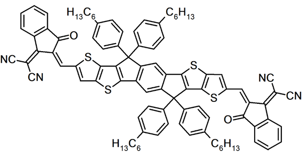
These are acceptors based on materials other than fullerene derivatives and are typically based on an acceptor-donor-acceptor (A-D-A) structure. The most efficient NFAs are those based on indacenodithiophene cores, such as ITIC and IT-2F.
Singlet Fission29
In singlet fission, absorption of a high-energy photon generates a singlet exciton that is then converted into two triplet excitons, hence generating two excitons from a single photon. This can then theoretically overcome the Shockley-Queisser limit on efficiency.
Ternary cells30,31
In ternary OPVs, three OSCs are used in the active layer instead of two, typically to improve the absorption of the cell in an attempt to boost efficiency. Ternary OPVs now have achieved efficiencies exceeding 14%32 and more details can be found in a previous ChemBorun blog post.
Molecular design33
The majority of highest efficiency OPVs have been obtained by donor-acceptor pairs specifically tuned to give highly complementary energy levels by chemical modification. This energy level tuning by molecular design is likely to be an area of significant focus as OPVs move forward.
Scalable deposition techniques
There has been recent focus on manufacture of OPVs using more scalable techniques than spin coating, such as spray coating,34 blade coating,35 slot-die coating36 and inkjet printing.37 This is likely to become increasingly relevant as OPVs move towards commercialisation.
-
References
- 01. Molecular Optimization Enables over 13% Efficiency in Organic Solar Cells, W. Zhao et al., J. Am. Chem. Soc., (2017), DOI:10.1021/jacs.7b02677.
- 02. Li, S. et al. A Wide Band-Gap Polymer with a Deep HOMO Level Enables 14.2% Efficiency in Polymer Solar Cells. J. Am. 03. Chem. Soc. jacs.8b02695 (2018). doi:10.1021/jacs.8b02695
- 03. Yan, C. et al. Non-fullerene acceptors for organic solar cells. Nat. Rev. Mater. 3, 72–83 (2018).
- 04. Brabec, C. J. et al. Polymer-Fullerene Bulk-Heterojunction Solar Cells. Adv. Mater. (2010). doi:10.1002/adma.200903697
- 05. Menke, S. M., Ran, N. A., Bazan, G. C. & Friend, R. H. Understanding Energy Loss in Organic Solar Cells: Toward a New Efficiency Regime. Joule 2, 25–35 (2018).
- 06. Proctor, C. M., Kuik, M. & Nguyen, T. Q. Charge carrier recombination in organic solar cells. Prog. Polym. Sci. 38, 1941–1960 (2013).
- 07. Shockley, W. & Read, W. T. Statistics of the Recombinations of Holes and Electrons. Phys. Rev. 87, 835–842 (1952).
- 08. Tang, C. W. Two-layer organic photovoltaic cell. Appl. Phys. Lett. 48, 183–185 (1986).
- 09. Halls, J. J. M. et al. Efficient photodiodes from interpenetrating polymer networks. Nature 376, 498 (1995).
- 10. Yu, G., Gao, J., Hummelen, J. C., Wudl, F. & Heeger, A. J. device structure consisted Polymer Photovoltaic Cells : Enhanced Efficiencies via a ( Ca The on a g | | g. Science (80-. ). 270, 1789–1791 (1995).
- 11. Shaheen, S. E. et al. 2.5% Efficient Organic Plastic Solar Cells. Appl. Phys. Lett. 78, 841–843 (2001).
- 12. Huang, Y., Kramer, E. J., Heeger, A. J. & Bazan, G. C. Bulk heterojunction solar cells: Morphology and performance relationships. Chem. Rev. 114, 7006–7043 (2014).
- 13. Ma, W., Yang, C., Gong, X., Lee, K. & Heeger, A. J. Thermally stable, efficient polymer solar cells with nanoscale control of the interpenetrating network morphology. Adv. Funct. Mater. 15, 1617–1622 (2005).
- 14. Park, S. H. et al. Bulk heterojunction solar cells with internal quantum efficiency approaching 100%. Nat. Photonics 3, 297 (2009).
- 15. Holliday, S., Li, Y. & Luscombe, C. K. Recent advances in high performance donor-acceptor polymers for organic photovoltaics. Progress in Polymer Science (2017). doi:10.1016/j.progpolymsci.2017.03.003
- 16. Cheng, P., Li, G., Zhan, X. & Yang, Y. Next-generation organic photovoltaics based on non-fullerene acceptors /639/301/299/946 /639/624/399 review-article. Nat. Photonics 12, 131–142 (2018).
- 17. Hou, J., Inganäs, O., Friend, R. H. & Gao, F. Organic solar cells based on non-fullerene acceptors. Nat. Mater. 17, 119–128 (2018).
- 18. Nakano, K. & Tajima, K. Organic Planar Heterojunctions: From Models for Interfaces in Bulk Heterojunctions to High-Performance Solar Cells. Adv. Mater. 29, (2017).
- 19. Cha, H. et al. An Efficient, ‘Burn in’ Free Organic Solar Cell Employing a Nonfullerene Electron Acceptor. Adv. Mater. (2017). doi:10.1002/adma.201701156
- 20. Servaites, J. D., Ratner, M. A. & Marks, T. J. Organic solar cells: A new look at traditional models. Energy Environ. Sci. (2011). doi:10.1039/c1ee01663f
- 21. Shockley, W. & Queisser, H. J. Detailed balance limit of efficiency of p-n junction solar cells. J. Appl. Phys. 32, 510–519 (1961).
- 22. Minnaert, B. & Burgelman, M. Efficiency Potential of Organic Bulk Heterojunction Solar Cells. Prog. Photovoltaics Res. Appl. 15, 741–748 (2007).
- 23. Gruber, M. et al. Thermodynamic effi ciency limit of molecular donor-acceptor solar cells and its application to diindenoperylene/C 60 -based planar heterojunction devices. Adv. Energy Mater. 2, 1100–1108 (2012).
- 24. Azzopardi, B. et al. Economic assessment of solar electricity production from organic-based photovoltaic modules in a domestic environment. Energy Environ. Sci. 4, 3741 (2011).
- 25. McDowell, C. & Bazan, G. C. Organic solar cells processed from green solvents. Current Opinion in Green and Sustainable Chemistry (2017). doi:10.1016/j.cogsc.2017.03.007
- 26. Li, Y. et al. Non-fullerene acceptor with low energy loss and high external quantum efficiency: towards high performance polymer solar cells. J. Mater. Chem. A 4, 5890–5897 (2016).
- 27. Liu, J. et al. Fast charge separation in a non-fullerene organic solar cell with a small driving force. Nat. Energy (2016). doi:10.1038/nenergy.2016.89
- 28. Cheng, P. et al. Realizing Small Energy Loss of 0.55 eV, High Open-Circuit Voltage >1 V and High Efficiency >10% in Fullerene-Free Polymer Solar Cells via Energy Driver. Adv Mater 29, (2017).
- 29. Roa, A. & Friend, R. H. Harnessing singlet exciton fission to break the Shockley-Queisser limit. Nat. Rev. Mater. 2, 1–12 (2017).
- 30. Ameri, T., Khoram, P., Min, J. & Brabec, C. J. Organic ternary solar cells: A review. Adv. Mater. 25, 4245–4266 (2013).
- 31. Yu, R., Yao, H. & Hou, J. Recent Progress in Ternary Organic Solar Cells Based on Nonfullerene Acceptors. Adv. Energy Mater. 1702814, 1–9 (2018).
- 32. Xiao, Z., Jia, X. & Ding, L. Ternary organic solar cells offer 14% power conversion efficiency. Sci. Bull. 62, 1562–1564 (2017).
- 33. Jackson, N. E., Savoie, B. M., Marks, T. J., Chen, L. X. & Ratner, M. A. The next breakthrough for organic photovoltaics? J. Phys. Chem. Lett. 6, 77–84 (2015).
- 34. Tao, W. et al. Fabricating High Performance, Donor–Acceptor Copolymer Solar Cells by Spray‐Coating in Air. Adv. Energy Mater. 3, 505–512
- 35. Zhao, W. et al. Environmentally Friendly Solvent-Processed Organic Solar Cells that are Highly Efficient and Adaptable for the Blade-Coating Method. Adv. Mater. 1704837, 1–7 (2017).
- 36. Larsen-Olsen, T. T. et al. Simultaneous multilayer formation of the polymer solar cell stack using roll-to-roll double slot-die coating from water. Sol. Energy Mater. Sol. Cells 97, 22–27 (2012).
- 37. Eggenhuisen, T. M.et al. Digital fabrication of organic solar cells by Inkjet printing using non-halogenated solvents. Sol. Energy Mater. Sol. Cells 134, 364–372 (2015).
-


